CMM vs Optical Measurement: Which Fits Your Tolerances
CMM excels at complex, high-precision geometries, while optical systems handle flat surfaces and vision checks. The right choice depends on part features, tolerance class, and production volume. Engineers must match the method to the critical dimensions.
- Choose coordinate measuring machines for complex three-dimensional features and tight tolerance classes.
- Select optical measurement for flat parts, surface checks, and high-volume production lines.
- Match the inspection method to the critical dimensions and part material to avoid false passes.
- Integrate the chosen system with cnc quality control workflows to maintain traceability.
- Review cnc quality certification requirements to ensure the inspection method meets contractual standards.
What Defines the Right Inspection Method
Engineers face a conflict when selecting an inspection tool because a part may pass on a flat surface but fail on a complex contour. The choice between coordinate measuring machines and optical measurement systems depends on geometry, tolerance, and production volume. A coordinate measuring machine, or CMM, uses a probe to touch a surface and collect points in three dimensions. Optical measurement uses cameras or lasers to capture images or profiles without contact. The two methods solve different problems.
A CMM excels when the part has multiple intersecting planes, internal bores, and external threads that must align precisely. It records the spatial relationship between features. Optical systems excel when the part is flat or has simple profiles. They capture the shape of the surface quickly. The decision rests on what the buyer needs to verify. If the tolerance is tight and the shape is complex, contact measurement is safer. If the shape is simple and the volume is high, contactless measurement is faster.
How CMM Works in Practice
A CMM sits in a controlled environment. Operators load a part, align it to reference planes, and run a program. The probe touches specific points. The machine calculates dimensions against CAD data. The environment matters. Temperature fluctuations change the size of the metal. A CMM room must be kept at a stable temperature to ensure the data is accurate.
This method works well for complex parts. Think of a valve body with internal bores and external threads. A CMM can verify the position of these features relative to each other. It checks concentricity, perpendicularity, and profile. The probe moves on linear axes. It stops at each programmed coordinate. It records the X, Y, and Z position.
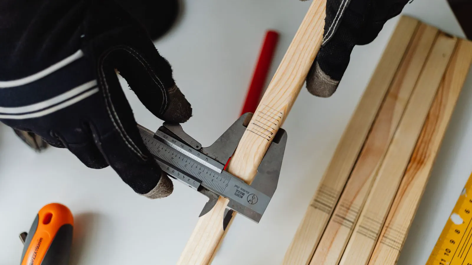
The probe speed matters. Touching a soft material like aluminum can leave marks. Hard materials like titanium are safer. The probe tip must be sharp but not brittle. A worn tip causes false readings. If the tip is dull, the probe may not register the exact center of a hole. If it is too sharp, it may chip the material. The operator selects the tip based on the material hardness and the feature size.
How Optical Measurement Works
Optical systems use light. They can be structured light, laser triangulation, or vision-based cameras. The system projects a pattern or beam onto the part. Cameras capture the deformation or profile. The software reconstructs the shape from the images.
This method is contactless. It works well for flat plates, PCBs, and sheet metal. It can check hole position, edge squareness, and surface flatness. The speed is high. A system can scan a large area in seconds. This speed is useful when a machine tool produces many parts per hour. The scanner can check every part on the line.
The main limitation is material reflectivity. Polished steel can reflect the light source, causing noise in the data. Matte finishes or black anodized surfaces work best. The system also struggles with transparent or translucent materials. Light passes through the material instead of reflecting off the surface. The camera sees the background or the other side of the part. This makes the data unreliable. Engineers often apply a matte coating to transparent parts before scanning.
CMM vs Optical Measurement: Comparison Table
| Option | Best for | Limitations |
|---|---|---|
| Coordinate Measuring Machine (CMM) | Complex 3D geometries, tight tolerances, multi-feature alignment | Slower speed, contact required, expensive setup for each part |
| Optical Measurement (Structured Light) | Flat surfaces, high-volume parts, non-contact inspection | Sensitive to reflectivity, limited depth range, less accurate for micro-features |
| Optical Measurement (Laser Line) | 2D profiles, edge checks, rapid line inspection | Limited to single-axis profiles, struggles with curved surfaces |
| Vision-Based Systems | Pattern recognition, hole position, surface defects | Requires good lighting, difficult for 3D depth without stereo pairing |
| Portable CMM | Field inspections, large structures, in-situ checks | Lower resolution than lab CMMs, sensitive to vibration |
When to Pick a CMM
Pick a CMM when the part is complex. If a bracket has three reference faces and ten critical dimensions, a CMM is the standard. It provides full three-dimensional data. The machine measures the part against the CAD model. It calculates the deviation for every feature.
This is common in aerospace and medical device manufacturing. Tolerances often fall in the micrometer range. A CMM can verify that a bearing seat is concentric with a housing bore. It checks the position of a thread relative to a mounting face. The data is detailed. The report shows exactly where the part deviates from the design.
The setup is more intensive. Each part may need a unique program. The measurement time is longer. For a single complex part, this is acceptable. For a thousand identical parts, it may be too slow. The operator must program the part carefully. They must define the reference points. They must set the probe paths. Errors in the program lead to errors in the data.
Engineers must ensure the CMM is calibrated. Regular checks with master balls are standard practice. The machine measures a sphere of known size. If the reading is off, the machine is out of calibration. The data must be traceable to national standards. This supports cnc quality certification requirements. The calibration certificate is part of the documentation.
When to Pick Optical Measurement
Pick optical measurement for high-volume production. If you are machining five thousand identical flat plates, a CMM will bottleneck the line. An optical scanner can inspect each part in seconds. The part stays on the fixture. The scanner moves above it. It captures the image. The software processes the data.
This fits well for cnc quality control in automotive or consumer electronics. The parts are often flat with simple holes or slots. The system checks position and size without touching the surface. It can check the distance between two holes. It can check the straightness of an edge.
The tolerance range is typically looser than a CMM. Optical systems can handle tolerances in the tens of micrometers. For sub-micrometer work, a CMM is usually required. The optical system samples the surface at a specific resolution. It cannot see every microscopic variation. The CMM touches the surface at specific points. It captures the exact location.
Lighting is a major factor. The part must be matte. If the surface is shiny, the system will struggle. Engineers often apply a temporary matte spray or use specific wavelengths. The spray covers the surface without damaging it. It is removed after inspection. The specific wavelength helps the camera distinguish the part from the background.
Integration with CNC Workflows
The inspection method must fit the production flow. A CMM is often a standalone check. The part leaves the machine, goes to the metrology lab, and returns. This adds time. The part sits in a queue. The operator waits. The part may be processed further before it is inspected. This creates a gap between machining and verification.
Optical systems can be installed at the machine tool. The part is machined, then the scanner checks it immediately. This enables inline cnc quality control. Defects are caught before the part moves to the next operation. The operator sees the result on the screen. They can stop the machine if the part is bad.
This reduces waste. If a part fails, it is scrapped or reworked immediately. The operator can adjust the tool offset or fix the fixture. This closes the loop quickly. The part does not move to the next station. The defect does not propagate. The cost is lower. The time is shorter.
Data integration is key. Both systems should export data to a central database. This creates a record for each part. The record includes the date, the operator, the machine, and the measurement values. This record supports audits and cnc quality certification. The data is available for review. If a customer asks for a trace, the engineer can provide the file.
Common Mistakes to Avoid
Engineers often buy the most expensive tool. This is a mistake. A high-end CMM is overkill for a simple flat part. The cost is high, and the speed is low. The part does not need that level of precision. A simpler optical system works well. The engineer should look at the tolerance. If the tolerance is loose, a high-end tool wastes money.
Another mistake is ignoring material reflectivity. A polished part will confuse an optical system. The data will be noisy. The engineer may reject good parts or accept bad ones. The reflection creates artifacts. The software cannot distinguish the part from the light source. The part must be prepared. A matte finish is required.
Setup errors are common. If the part is not clamped correctly, the measurement is wrong. Both methods require a stable fixture. For optical systems, the part must not move during the scan. Even a small vibration changes the data. The fixture must hold the part firmly. The part must not shift.
Finally, engineers forget calibration. Both CMMs and optical systems drift over time. Without regular calibration, the data is unreliable. This breaks the traceability chain. The calibration schedule must be followed. The records must be kept. If the system is out of calibration, the data is invalid. The parts must be re-inspected.
Final Selection Criteria
The decision comes down to three factors.
- Tolerance class. Sub-micrometer work needs a CMM. Tens of micrometers can use optical.
- Part geometry. Complex 3D features need a CMM. Flat parts work well with optical.
- Production volume. Low volume favors CMM. High volume favors optical.
Engineers should look at the critical dimensions. If the critical dimension is a flatness check on a large plate, optical is better. The scanner covers the whole surface. It finds the high and low spots. If it is the position of a small bore relative to a surface, a CMM is better. The probe touches the bore wall. It measures the exact position.
Match the tool to the data needed. Do not buy a system that gives more data than you need. Do not buy a system that cannot measure the features you care about. The right choice improves cnc quality control. It ensures that parts meet specifications. It supports cnc quality certification by providing reliable, traceable data. It reduces scrap and rework. It saves time and money.
Frequently asked questions
Can an optical system replace a CMM for all parts?
No. Optical systems are less accurate for complex three-dimensional features and tight tolerances. A CMM is still required for high-precision work.
What is the biggest issue with optical measurement on shiny parts?
Reflectivity is the main issue. Shiny surfaces reflect the light source, which creates noise in the data and can lead to false readings.
How often should a CMM be calibrated?
CMMs require regular calibration, often with master balls, to ensure accuracy. The frequency depends on the manufacturer and industry standards.
Does cnc quality certification specify which inspection tool to use?
Certification standards like ISO 9001 require documented and traceable inspection methods. They do not mandate a specific tool, but the method must be validated for the part.
Is a portable CMM a good option for large parts?
Yes. Portable CMMs are useful for large structures that cannot fit in a lab CMM. They offer lower resolution but provide 3D data in the field.