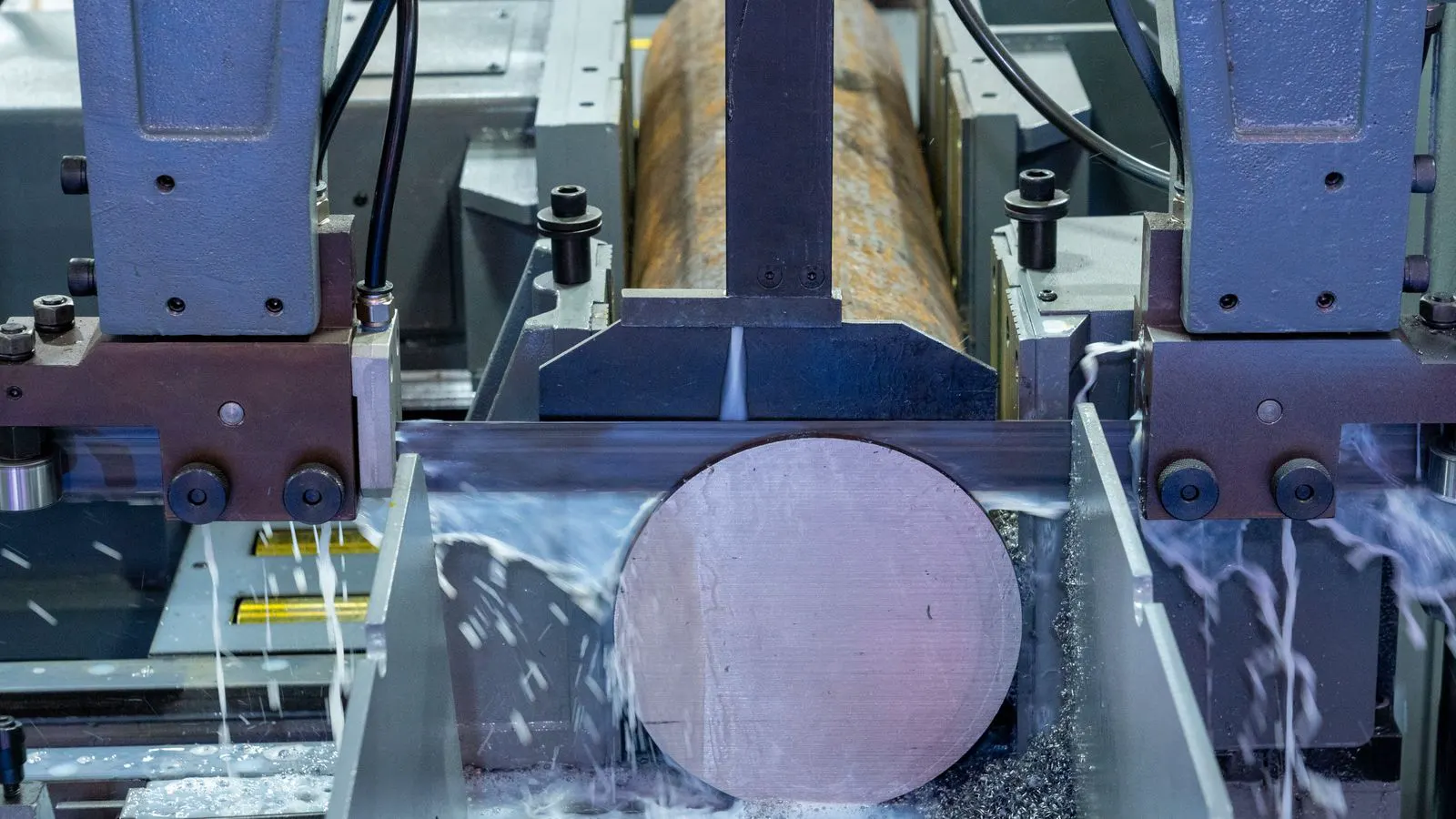
Pre-Production Checklist for CNC Machined Metal Components

A structured CNC machining checklist helps engineers and buyers verify material, tolerances, and fit before production. This guide provides a step-by-step audit of design, inspection, and quality control to prevent costly errors.
- Verify material certifications and dimensional tolerances before cutting.
- Use a structured CNC machining checklist to catch design and inspection gaps.
- Align production QC metrics with customer requirements to avoid rework.
- Document all inspection results for traceability and future reference.
- Review fit and function requirements to ensure parts meet operational needs.
Why a Pre-Production Checklist Matters
A CNC machining checklist is the final line of defense before steel, aluminum, or titanium is cut. It bridges the gap between a design file and a finished component. Skipping this step often leads to scrapped parts, expensive rework, or failed customer inspections.
This guide provides a structured audit for engineers, buyers, and shop managers. It focuses on practical verification steps for metal parts inspection and production QC. Use it as a copyable template for your internal reviews.
Verify the Design and Material Specifications
Before the first tool touches the workpiece, the design must be stable and the material must be defined. Ambiguity here is the most common cause of production failure.
- Design Freeze Confirmation: Ensure the CAD file is the final version. No revisions should be accepted after the checklist is completed.
- Material Grade Identification: Confirm the specific alloy, such as 6061-T6 aluminum or 17-4PH stainless steel. Generic “aluminum” descriptions are not sufficient for critical parts.
- Heat Treatment Verification: If the part requires a specific temper, confirm the certificate of analysis (CoA) is available for the specific batch.
Red Flag: The drawing shows “304 Stainless” but the material is ordered as “316 Stainless.” This is a common mix-up that changes corrosion resistance and machining behavior.
Check Tolerances and Geometric Dimensional Control
Tolerances define the limits of acceptance. If the tolerance is too tight for the chosen material or machine, the part will fail. If it is too loose, the assembly may not fit.
| Feature Type | Typical Tolerance Range | Inspection Method |
|---|---|---|
| General Machined Dimensions | ±0.05 mm to ±0.10 mm | Calipers, Micrometers |
| Critical Fit Dimensions | ±0.01 mm to ±0.025 mm | CMM, Pin Gauges |
| Hole Positioning | ±0.05 mm | CMM, Hole Gauges |
| Surface Finish | 0.8 µm to 3.2 µm Ra | Surface Roughness Tester |
Red Flag: A tolerance of ±0.005 mm is specified for a feature on a standard milling machine without a note for a CMM inspection or special tooling. This often leads to rejected parts.
Validate Inspection and Measurement Methods
Knowing what to measure is only half the battle. You must also know how to measure it accurately.
- CMM Plan Review: If a Coordinate Measuring Machine is required, ensure the program is written and tested against the CAD model.
- Gauge Design: For critical fits, verify that the custom gauge or ring gauge is available.
- Surface Finish Verification: Confirm the roughness tester is calibrated. A visual check is not sufficient for production QC.
Red Flag: The drawing calls for a surface finish of 0.4 µm, but the inspection plan relies on a visual inspection. This is a mismatch that will fail during customer audit.
Confirm Fixturing and Machining Strategy
The way the part is held during machining affects its final geometry. A part that twists in the vise will have warped dimensions.
- Fixturing Plan: Review the drawing for recommended clamping locations. Ensure the fixturing does not interfere with machined surfaces.
- Stress Relief: For thick or complex parts, confirm if stress relief heat treatment is required before or after machining.
- Tooling Verification: Check that the required tooling is available and compatible with the machine’s spindle and work envelope.
Red Flag: The design has a thin web or thin wall. If the fixturing plan does not account for vibration or deflection, the part may crack or go out of tolerance during cutting.
Review Surface Finish and Coating Requirements
Surface finish affects aesthetics, wear, and corrosion resistance. Coatings add complexity and require additional QC steps.
- Finish Class: Confirm the required Ra or Rz value.
- Coating Type: If plating or anodizing is required, verify the thickness and color specifications.
- Deburring: Ensure the drawing specifies deburring requirements for all edges. Sharp edges are a safety hazard and a common customer complaint.
Red Flag: The part is to be anodized, but the drawing does not specify the anodizing type (Type I, II, or III). This leads to inconsistent surface hardness and color depth.
Finalize Production QC and Documentation
The last step is ensuring that the shop will document the inspection results. Traceability is critical for aerospace, medical, and automotive industries.
- First Article Inspection (FAI): Confirm that a full FAI report will be generated for the first part.
- CMM Data: Ensure the shop will provide the raw CMM data, not just a pass/fail report.
- Material Certs: Verify that the CoA and heat treatment certs will be attached to the final delivery.
Red Flag: The customer requires a specific QC standard, such as AS9100 or ISO 9001, but the shop does not have a documented process for meeting it. This is a major risk for compliance.
Common Mistakes to Avoid
Even with a good checklist, errors happen. Watch for these frequent pitfalls:
- Unit Confusion: Mixing up inches and millimeters on the drawing.
- Missing Datum References: Tolerances without proper datum definitions are meaningless.
- Assumed Tolerances: Assuming general tolerances apply to critical features when they are not explicitly stated.
- Ignoring Scale: A small tolerance error on a large part can be catastrophic.
Conclusion
A robust CNC machining checklist transforms production from a guessing game into a controlled process. By verifying materials, tolerances, inspection methods, and documentation, you reduce the risk of failure. Use this template to standardize your pre-production reviews and ensure every metal part meets quality expectations.
Frequently asked questions
How often should I run a CNC machining checklist?
Run it before every new job. For production runs, run a lighter version for each batch to catch drift or setup errors.
What is the difference between a FAI and a routine inspection?
A FAI is a comprehensive inspection of the first part to validate the process. Routine inspections are spot checks to monitor consistency during production.
Can I use a visual check for surface finish?
No. Visual checks are subjective and unreliable. Use a calibrated surface roughness tester for production QC.
Why is the material certificate important?
The certificate proves the alloy composition and heat treatment history. This is critical for safety-critical applications and traceability.
What if the tolerance is not on the drawing?
Do not assume. Ask the designer for clarification. If no tolerance is given, standard general tolerances may apply, but this should be confirmed in writing.