How to Design Parts for Efficient CNC Tool Pathing
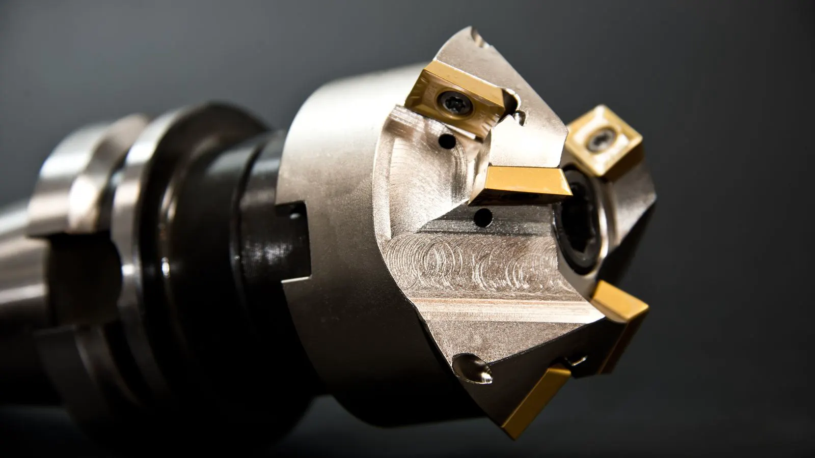
Efficient CNC part design starts with simple geometry, accessible features, and standard stock sizes. By planning tool access before drafting, engineers reduce setup time, lower tool wear, and cut machining costs without sacrificing part function or tolerance.
- Simple, accessible geometry directly reduces tool path complexity and cycle time
- Standard stock sizes and uniform wall thicknesses lower setup and material costs
- Avoid deep pockets, sharp internal corners, and thin features that force slow, fragile tooling
- Validate tool path accessibility early in the CAD model before releasing for manufacturing
- Coordinate design features with the machine's axis capabilities to prevent secondary operations
Prerequisites: What You Need Before Changing the Design
Before modifying geometry for CNC tool pathing, confirm the part’s functional requirements, material, and tolerance stack. A part that cannot perform its job no matter how easy it is to machine is not a good design. Open the CAD file and identify every feature that affects tool access, depth, and repeatability.
Have the material and stock size in front of you. A machinable aluminum part behaves differently from a hardened steel or titanium component. The tool path changes when the material changes. If the buyer has not specified the material, state your assumptions in the drawing so the shop can flag them before cutting.
This step prevents a common failure mode. Engineers often design a feature that is geometrically possible but physically impossible to reach with standard end mills or face mills. Catching that in CAD takes minutes. Catching it on the floor takes hours.
Step 1: Standardize Stock and Feature Orientations
Select a stock size that matches the part’s outer dimensions with minimal machining allowance. Avoid custom bar or plate sizes unless the function demands it. Standard stock reduces ordering lead time and simplifies fixturing.
Orient the part so the largest flat face is the primary machining plane. Most CNC machines are rigid and most accurate when the workpiece sits flat on a table or in a vise. If you design with a curved face as the primary reference, the shop must machine that curve first, which changes how every downstream feature is held.
The reason for this step is that tool pathing assumes a known reference plane. When the reference is flat and standard, the CAM software generates cleaner, more predictable paths. When the reference is irregular, the tool must compensate for the part’s position more aggressively, which increases cycle time and wear.
Step 2: Open Up Internal Features
Design pockets, slots, and holes so that a tool can enter and exit without touching the part’s outer walls. Use chamfered or filleted entry transitions. Keep the pocket depth to diameter ratio low when possible.
Deep pockets are a common source of tool path problems. A long, narrow slot requires a small tool to reach the bottom. A small tool is fragile and slow. The machine must use a shallow, slow cut to avoid the tool breaking. The result is a longer cycle time and a higher chance of tool failure.
The reason for this step is that tool diameter limits how deep a feature can be machined in one setup. A 10 mm end mill can clear a 10 mm diameter hole cleanly. A 1 mm drill can only reach a 1 mm diameter hole. If the design asks for a 2 mm diameter hole in a 40 mm deep pocket, the tool path becomes a series of small, slow cuts that wear the tool quickly.
Step 3: Use Uniform Wall Thickness
Keep walls, ribs, and thin sections at a consistent thickness. Avoid sudden step changes in wall thickness. A wall that is 12 mm thick on one side and 3 mm on the other forces the machinist to use different tools and different cuts for each side.
The reason for this step is that uniform material removal reduces thermal distortion. When the part cools unevenly, the tolerance stack shifts. Uniform walls also allow the CAM system to use a single tool for multiple features, which reduces tool changes and setup time.
A practical check: run a section view through every wall. If the material thickness jumps by more than 50 percent between adjacent features, ask whether that feature can be relocated or merged.
Step 4: Avoid Sharp Internal Corners
Replace sharp 90 degree internal corners with small fillets or chamfers. The radius of the fillet should match the smallest tool that will be used to machine that feature. If you cannot reach a corner with the tool you need, the corner cannot be machined to spec.
The reason for this step is that a sharp internal corner is a tool path dead zone. A flat end mill leaves a small uncut area at the corner. To clear that area, the shop must use a smaller tool or a ball nose, which is slower and more expensive. The fillet removes the need for that extra operation.
The size of the fillet matters. A 1 mm fillet is easy to machine with a 2 mm end mill. A 0.2 mm fillet on a hardened steel part is nearly impossible without a specialized tool and a very slow cut. Match the fillet radius to the tool you actually have.
Step 5: Plan Tool Access Before Drafting
Before you finish the CAD model, simulate the tool path in your head. For every feature, ask: which tool enters from where? Does it touch the part on the way in or out? Can the tool exit without hitting the fixture?
The reason for this step is that tool access is the single biggest factor in tool path efficiency. A feature that looks simple in the CAD model can require a multi-axis move, a tool change, or a part flip if the access path is blocked. By planning access early, you avoid these complications.
A useful habit: label every feature in your CAD model with the tool type and entry direction you intend to use. This note becomes a direct input to the CAM operator. It turns a guess into a spec.
Step 6: Align Features with Machine Axes
Design features that align with the machine’s primary axes. A hole that is drilled perpendicular to the part’s top face is easy. A hole that is drilled at a 30 degree angle requires a tilt table or a multi-axis setup, which is slower and less rigid.
The reason for this step is that axis-aligned features allow the machine to use its native motion. A three-axis machine is fast and rigid when the tool moves along X, Y, and Z. When you ask it to tilt or rotate, the motion becomes a combination of axes, which introduces play and reduces repeatability.
If a feature absolutely must be angled, state the angle on the drawing and specify whether the shop will tilt the table, tilt the spindle, or use a secondary operation. This prevents the shop from guessing and forces the design to account for the extra setup.
Step 7: Reduce Feature Count
Every feature on a part adds a tool path, a tool change, and a chance for error. Remove features that do not affect function, fit, or form. A decorative rib, an unnecessary chamfer, or a hole that is never drilled all add cost without adding value.
The reason for this step is that feature count directly drives cycle time. A part with 40 features takes longer to machine than a part with 20 features of the same size. The CAM system must calculate a path for each feature, and the operator must verify each path. Fewer features means less calculation, less verification, and less risk.
A practical rule: if a feature cannot be tested on a prototype without affecting the part’s function, it should not be on the drawing. This applies to decorative features, non-functional chamfers, and holes that are never used.
Common Mistakes That Break Tool Path Efficiency
- Designing deep, narrow pockets that require small, slow tools
- Placing sharp internal corners that cannot be reached by any standard tool
- Using non-standard stock sizes that complicate ordering and fixturing
- Orienting the part so the primary reference face is curved or irregular
- Adding features that require secondary operations without stating the setup
- Ignoring tool access and assuming the CAM software will find a path
- Letting wall thickness vary wildly across the part
Final Verification: Run a Tool Path Check Before Releasing
Before you release the drawing for manufacturing, open the CAD model in a CAM environment or a tool path simulator. Generate a preliminary tool path for every feature. Check the tool entry and exit points. Look for collisions with the fixture or the part itself.
The reason for this step is that a tool path check catches errors that are invisible in the CAD model. A feature that looks accessible in the 3D view may be blocked by a rib or a boss when the tool enters. A tool path simulator shows you the actual motion, which is the only way to know if the path is feasible.
If the tool path check fails, go back to the CAD model and adjust the geometry. Do not ask the shop to “make it work” with a different tool or a different setup. Fix the design. A five minute change in CAD saves a five hour change on the floor.
Comparison of Design Choices and Their Impact
| Design Choice | Tool Path Impact | Manufacturing Impact |
|---|---|---|
| Flat reference face | Clean, predictable paths | Faster setup, better accuracy |
| Deep narrow pockets | Small slow tools, long cycle | Higher tool wear, longer cost |
| Sharp internal corners | Extra tooling or secondary op | More tool changes, more cost |
| Uniform wall thickness | Single tool for multiple features | Less thermal distortion |
| Axis-aligned holes | Native machine motion | Faster, more rigid, less play |
| Non-standard stock | Complex fixturing | Longer lead time, higher cost |
Frequently asked questions
Can I design a part with a curved reference face and still get efficient tool paths?
Yes, but the shop will need to machine that curve first, which changes the reference for every downstream feature. This adds setup time and reduces accuracy compared to a flat reference face.
How do I know if a pocket is too deep for a standard tool path?
A general rule is that the depth to diameter ratio should be low. If the pocket is much deeper than the tool diameter, the tool will require many small, slow cuts to reach the bottom. This increases cycle time and tool wear.
Does adding a fillet to an internal corner always make the part easier to machine?
A fillet removes the need for a smaller tool to reach a sharp corner. The size of the fillet matters. A small fillet that matches the tool diameter makes the feature easy to machine. A very small fillet still requires a small tool and a slow cut.
What is the fastest way to verify tool path accessibility before releasing a drawing?
Open the CAD model in a CAM environment and generate a preliminary tool path. Check the tool entry and exit points for collisions. This catches errors that are invisible in the 3D view.
Can I reduce feature count without affecting the part's function?
Yes, if the feature does not affect fit, form, or function. Remove decorative ribs, non-functional chamfers, and holes that are never drilled. This reduces cycle time and risk without changing the part's performance.