Future of CNC DFAM: Automation and Digital Design
DFAM CNC is moving from static checklists to digital validation and automated tooling. This guide outlines five shifts in automation and digital design. It explains how to prepare part geometry, materials, and data for these changes to avoid cost overruns.
- DFAM CNC now relies on digital simulation before metal is cut.
- Automation changes tooling choices because the machine does the selection.
- Part geometry must support automated setup and probing.
- Designers and machinists share data through digital twins and CAD models.
- Preparation means moving checks from the shop floor to the design phase.
How Digital Simulation Changes DFAM CNC
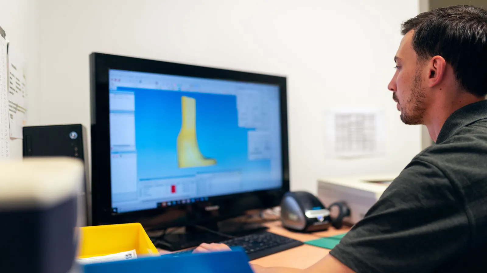
DFAM CNC is no longer just a checklist applied after a part is drawn. The shift toward digital simulation means engineers can test manufacturability inside the CAD environment. A part that looks clean on a 2D print may still trap coolant, hide a feature from a probe, or force a long tool path.
Modern DFAM processes integrate these checks into the design workflow. A designer can run a simulation that shows if a deep pocket can be reached with a standard end mill. The software can flag features that will cause vibration or require a manual change of tooling. This reduces the risk of late-stage redesigns.
Consider a bracket with a deep slot. On paper, the slot width and depth seem manageable. When a simulation runs, the software might show that the tool path causes chatter on the vertical walls. The designer can then adjust the slot width, add chamfers, or change the tooling strategy before any metal is cut. This specific type of feedback is impossible to get from a static drawing.
For buyers, this means the definition of “manufacturable” has moved upstream. The cost of a design error now appears in the digital model, not in the scrap bin. The goal is to catch issues while the part is still easy to change. When a design is approved, it is not just a shape; it is a set of instructions that the machine will follow. If the instructions are flawed, the part will fail. Simulation allows the team to validate those instructions in a risk-free environment.
The Role of Automation in Design Choices
Automation in CNC machining is more than just running the machine unattended. It changes how parts are designed for tooling and setup. When a machine can change tools automatically, the design can rely on standard tool libraries instead of custom holders.
Consider a bracket with multiple features. A traditional setup might require a machinist to manually select a specific tool for each hole. An automated cell can handle this sequence without intervention. The design can therefore use standard tool sizes and depths. This reduces the need for exotic tooling that is hard to source.
If a design calls for a 45-degree chamfer on every edge, an automated cell might struggle if the tooling is not standardized. The designer should specify standard chamfer angles that match the available tool library. This simplifies the CAM program and reduces the chance of tool breakage during automatic changes.
Automation also supports multi-axis machining. A part designed for a 5-axis machine can be held in a single setup. The tooling must be chosen to avoid collisions with the part and the fixture. DFAM CNC now requires designers to think about the whole tool envelope, not just the individual cuts. A designer might specify a large face mill for a roughing pass. If the part has tall walls, the simulation might show that the face mill hits the fixture. The designer then switches to a smaller tool or adjusts the fixture design.
How Probing Changes Part Geometry
Fixed probing is becoming standard in high-precision cells. The machine measures the part before cutting to confirm its location and orientation. This changes how part features are designed.
A part with a unique, irregular shape is harder to probe. The machine needs reference features that are stable and easy to locate. Flat surfaces, holes, or specific chamfers serve as these references. If a part has no good reference points, the setup becomes slow and prone to error.
Designers should include dedicated probing features where possible. These do not need to be large. A small flat or a counterbore can give the machine what it needs. This small addition prevents long setup times and improves repeatability.
For example, a housing with a complex internal channel might be difficult to locate automatically. Adding a small, flat surface on the top face allows the probe to touch it quickly. If the part is rotated for a second operation, a different reference feature is needed. The designer must ensure that these features are accessible and not easily damaged during handling.
Probing also affects tolerance stack-up. If a part is large and has a long runout, the machine might not be able to hold it within tolerance without re-probing. The design should account for this. A part with multiple features in different planes might require more probing points than a simple block. The designer should limit the number of critical reference planes to reduce setup complexity.
The Digital Thread and Data Flow
The digital thread connects the design file directly to the machine control. This flow eliminates manual re-entry of data. The CAD model is converted to CAM, which drives the machine. Errors in one step are visible in the next.
This integration requires clean data. The CAD model must have accurate dimensions and tolerances. Any ambiguity in the drawing will carry through the digital thread to the machine. A missing tolerance on a hole can cause the CAM software to guess, leading to a bad cut.
For suppliers, this means the data quality is part of the DFAM process. A clean model is as valuable as the part itself. Buyers should expect suppliers to validate their own digital data before quoting a job.
If a CAD model has a sketch with a missing constraint, the CAM software might create a tool path that cuts through the air. This wastes machine time and can damage the tool. The designer must ensure that every feature is fully defined. Dimensions should be explicit. Tolerances should be clear. Notes should explain any special requirements.
The digital thread also allows for rapid iteration. If a part needs a change, the designer updates the model. The CAM software regenerates the tool path. The machine receives the new program. This cycle is much faster than redrawing the part and manually reprogramming the machine. For buyers, this means faster response times for design changes.
Five Shifts Buyers Should Plan For
The evolution of DFAM CNC is not a single event. It is a series of changes that affect how parts are designed and produced.
- Simulation Before Cutting: Every part gets a digital test. The designer checks tool paths and collisions. This replaces guesswork with data.
- Automated Tooling Selection: The machine selects tools from a standard library. Designers must choose features that fit these standard tools.
- Probing-Ready Geometry: Parts need reference features for automatic setup. Irregular shapes are harder to machine automatically.
- Digital Data Integrity: The CAD model must be perfect. Errors in the file become errors in the part.
- Shared Responsibility: Designers and machinists work from the same data. The line between “design” and “manufacture” blurs.
These shifts require a new way of thinking. Designers are no longer just creating shapes. They are creating instructions for machines. Machinists are no longer just cutting metal. They are validating digital data. The collaboration between these roles is essential for successful DFAM CNC.
How to Prepare Your Part Designs
Preparing for these shifts requires a change in how you think about part geometry.
First, review your drawings for standard tool compatibility. If a feature requires a long, thin tool for a deep hole, consider if a different design works. A stepped hole or a different material might allow a standard tool. For instance, a 50mm deep hole with a 10mm diameter might require a 4:1 aspect ratio tool. This is prone to breakage. A stepped hole, where the first 20mm is 15mm in diameter and the next 30mm is 10mm, allows the use of a larger, stiffer tool for the first part of the cut. This reduces the risk of tool failure.
Second, add probing features. Look for flat surfaces or holes that the machine can use for setup. If the part is irregular, add a dedicated locating pin or a flat pad. This small change can save setup time. Ensure that these features are not critical to the part’s function. They should be easy to probe and not easily damaged.
Third, check your tolerances. If a tolerance is not critical, remove it. Loose tolerances are easier to machine. They also reduce the risk of a part failing a probe check. For example, a flatness tolerance of 0.05mm on a large surface might be difficult to hold. If the part’s function allows it, a tolerance of 0.1mm would be easier to machine and probe.
Fourth, think about the tool envelope. When designing for multi-axis, make sure the tools do not hit the part. A simulation will catch this, but a good designer will see it too. Visualize the part on the machine. Look at the tool holders. Check the fixture. If a tool is likely to hit the part, change the design. Add a larger clearance hole or reduce the height of the feature.
Fifth, clean up your data. Ensure the CAD model has no missing dimensions. Use clear notes for features that need attention. A clean model is the first step in a smooth digital thread. Remove any unnecessary features. Simplify the geometry. Use standard features where possible.
| Design Shift | What Changes | How to Prepare |
|---|---|---|
| Digital Simulation | Tool paths are tested before cutting | Run simulations on complex parts |
| Automated Tooling | Standard tools handle most jobs | Use standard tool sizes in design |
| Probing Features | Machine locates part automatically | Add reference flats or holes |
| Data Integrity | CAD drives the machine directly | Clean up models and tolerances |
| Shared Workflow | Design and manufacture share data | Involve machinists early in design |
The table above summarizes the key shifts. Each one requires a small change in how you design. The cumulative effect is a part that is cheaper and faster to make.
Final Thoughts
DFAM CNC is changing because the tools are changing. Automation and digital design are moving the focus from the shop floor to the screen. The part is made in the model before it is made in metal.
Buyers should not wait for these changes to happen to them. Start by checking your current designs against these new standards. Look for features that are hard to automate. Add the small details that make a part easier for a machine to handle.
The goal is not to make the design complicated. The goal is to make the design clear. A clear design is a cheap design. When the design is clear, the machine can do its job quickly and accurately. This is the essence of DFAM CNC.
Frequently asked questions
What is the biggest benefit of digital DFAM?
Digital DFAM catches design errors before metal is cut. This reduces scrap and rework. It saves time and money.
Does automation mean I should not design for a specific tool?
No. You should design for standard tools that are common in automated cells. This makes the part easier to machine.
What if my part is very irregular?
Add reference features for probing. A flat surface or a hole helps the machine find the part. This makes automation possible.
How do I clean up my CAD model for the digital thread?
Remove missing dimensions and loose tolerances. Make sure the model matches the drawing. This prevents errors in the machine file.
Is DFAM CNC only for big companies?
No. The principles apply to all sizes. Small parts can use standard tools and probing features. The goal is the same for everyone.