Buyer's Guide to CNC DFAM Software for Design Teams
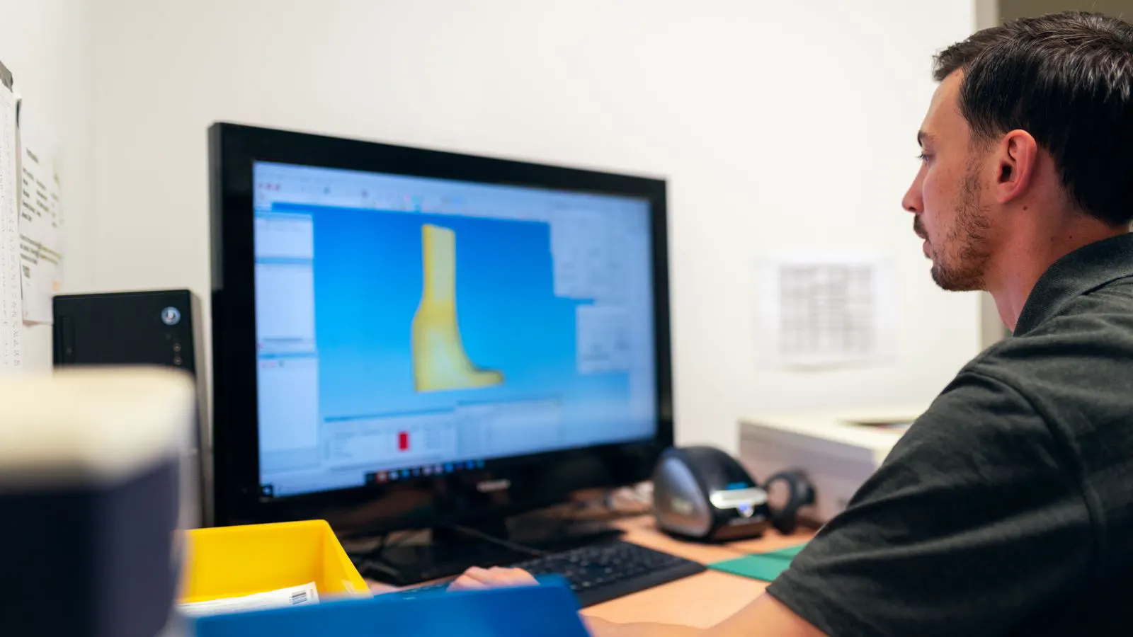
Procurement managers should evaluate cnc design guidelines software based on its ability to integrate with CAD, support specific materials, and flag common errors. The right tool reduces rework and shortens quote times for the design team.
- Prioritize software that connects directly to your team's CAD environment to avoid manual file conversions.
- Verify the tool supports the specific materials and processes your team machines, such as stainless steel or aluminum.
- Test the tool with historical bad parts to see if it catches the same errors before release.
- Assess the cost against the reduction in engineering rework and supplier communication time.
- Ensure the output generates clear, actionable reports that engineers and machinists can both understand.
Why software changes the design phase
Manual checks catch some errors, but they miss others. A design team may spend hours checking tolerances while overlooking a thin wall that will not hold up during roughing. DFAM software automates this review. It scans the geometry against standard cnc design guidelines and flags issues before the file leaves the CAD system.
This matters for procurement managers. Every rework cycle delays the project. It increases internal labor costs and strains relationships with machine shops. A tool that catches a problematic feature at the design stage saves money and time. The goal is not to replace engineers. It is to give them a second set of eyes that never gets tired.
What to look for in the interface
The interface must fit the team’s existing workflow. If the software requires a separate login or a new file format, adoption will be slow. Engineers will work around it.
Look for a plugin or add-in that runs inside the native CAD environment. The tool should highlight issues directly on the model. It should provide a tooltip or a small window with a specific reason. For example, it might point to a small internal hole and note that the minimum diameter is too small for a standard end mill.
The report should be simple. A long PDF with technical jargon will sit in a folder. A short list with screenshots and clear action items will get fixed. The tool needs to speak the language of the shop floor and the language of the design room in the same document.
Evaluating material and process support
Not all parts are the same. A part made from mild steel behaves differently than a part made from Inconel. The tool must understand these differences. Check if the software includes a library for your primary materials.
It should flag features that are difficult to machine in specific alloys. For instance, thin features in stainless steel are prone to spring back during cutting. The software should warn the user if a wall thickness is below a recommended minimum for that material.
Also check process support. Does it cover milling, turning, and drilling? Some tools focus only on milling. If your team sends parts to a shop that uses lathes, the tool might miss turning-specific issues, such as undercuts that prevent a chuck from gripping the part.
Integration with your CAD and PLM systems
Integration is the make or break factor for many teams. If the DFAM check happens outside the design process, it becomes an extra step that gets skipped under pressure.
The best tools run automatically when the part is saved or when a specific status is reached in the PLM system. This creates a gate. The part cannot move to the next stage until the DFAM check passes or is overridden with a documented reason.
This requires some setup. You need to map the data fields. You need to define which rules apply to which part families. If your team uses a PDM system, make sure the tool can read the metadata. For example, the software should know that a part designated as “production” requires a stricter check than a part designated as “prototype.”
How to test the tool with real parts
Do not rely on vendor demos. Demos show perfect parts. They do not show the messy, imperfect models your team produces. Bring a portfolio of parts that failed in the past.
Select parts that had issues during machining. Look for parts that required rework, parts that arrived with dimensional errors, or parts that were rejected by the buyer. Run these through the trial version of the software.
See what it catches. If it misses a known error, that is a red flag. If it catches the known error but also flags something else that is actually fine, that is a false positive. Balance is key. You want a tool that is smart enough to catch problems but not so aggressive that it slows the team down with noise.
Track the number of false positives per part. If the tool generates five warnings for every part, engineers will ignore it. If it generates zero warnings for a bad part, it is useless. You need a signal-to-noise ratio that your team can live with.
Cost and total value
The license fee is only part of the cost. Consider the implementation cost. Who will configure the rules? How long will it take to train the team?
Compare this against the cost of rework. One reworked part might cost hundreds or thousands of dollars, depending on the material and the complexity. If the software prevents even a few reworks per quarter, it pays for itself.
Look for pricing models that scale. If your team grows, will the cost jump significantly? Some tools charge per user, others per part. Choose the model that matches your growth plan. Also check for support costs. If the rules need updating for new processes, is that included, or is it a separate fee?
The criteria table
Use this table to compare vendors. Print it out and fill in the blanks during your evaluation.
| Criterion | What to look for | Why it matters |
|---|---|---|
| CAD Integration | Native plugin, no file export required | Ensures checks happen in the workflow, not after |
| Material Library | Support for your primary alloys and plastics | Prevents generic rules that miss material-specific issues |
| Report Clarity | Actionable list with visuals, not just text | Reduces time spent interpreting the results |
| Rule Customization | Ability to add or remove specific checks | Allows you to match the tool to your shop’s capabilities |
| Automation | API or trigger-based execution | Removes manual steps and prevents skipped checks |
| Support | Training, rule updates, and technical help | Ensures the tool stays relevant as processes change |
Final decision checklist
Before you sign the contract, run through this list.
- Does the tool run inside our current CAD software?
- Can we customize the rules for our specific materials?
- Did the trial catch errors in our historical bad parts?
- Is the report format acceptable to both engineers and machinists?
- What is the total cost including setup and training?
- Can we integrate it with our PLM or PDM system for automated checks?
- Is there a clear support plan for rule updates?
If the answer to most of these is yes, the tool is likely a good fit. If the answer is no to the integration question, walk away. A powerful tool that lives outside the workflow will not save you time. It will just add another task to the list.
Common mistakes to avoid
One mistake is buying a tool that is too generic. It covers everything but does not do anything well. It flags standard tolerances that your shop handles daily. It does not catch the subtle geometric issues that cause real problems.
Another mistake is ignoring the training. The software is only as good as the people using it. If engineers do not understand why a warning appeared, they will dismiss it. Invest time in explaining the logic behind the rules. Show them how a flagged feature would fail on the machine.
Finally, do not treat the tool as a final gate. It is a filter. It catches obvious issues. It does not replace human judgment. A senior engineer should review the flagged items. The software speeds up the process, but it does not make the decision.
The bottom line
Choosing the right cnc design guidelines software is about fit, not just features. The best tool is the one that fits your team, your materials, and your processes. It should run quietly in the background and only speak up when it matters.
Start with a small pilot. Pick one team and one product family. Run the tool for a few months. Measure the reduction in rework. Measure the time saved in design reviews. Use that data to make a decision. Do not guess. Let the numbers tell you if the tool is worth the investment.
If you choose well, your design team will work faster. Your suppliers will get cleaner files. Your parts will arrive on time. That is the real value of dfam for cnc. It is not about the software. It is about the parts you ship.
Frequently asked questions
How long does it take to implement DFAM software?
Implementation varies based on integration needs. A simple plugin might take a few days. A full integration with a PLM system can take several weeks.
Can DFAM software replace engineering judgment?
No. It catches known geometric issues based on rules. It does not understand the specific context of a project. Engineers must review the flags and make the final call.
What is the difference between DFAM and DFM?
DFM is the broader process of designing for any manufacturing method. DFAM is specifically focused on CNC machining. DFAM tools check for milling and turning issues, while DFM might also check for casting or molding.
Do I need to buy a license if my team is small?
Some vendors offer per-user or per-part pricing. If you have a small team, look for entry-level plans. The value often comes from the consistency of checks, not the number of users.
How do I handle false positives from the software?
Most tools allow you to suppress a warning for a specific reason. You should document the reason. This keeps the log clean and helps you tune the rules over time.