CNC Milling vs Turning: Tool Selection Guide
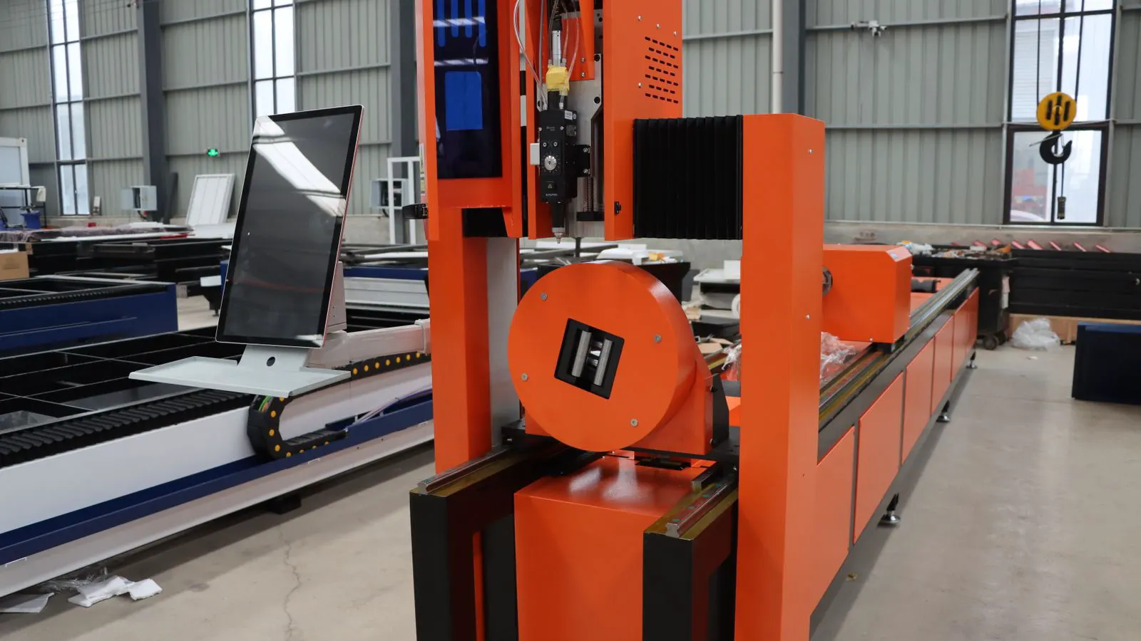
This CNC tooling guide explains how to select the right end mills and turning inserts. It covers material hardness, geometry, and chip control to help engineers match tools to their specific machining tasks.
- Match cutting geometry to the part shape, not just the material grade.
- Verify insert geometry and coating chemistry for each alloy family.
- Check tool holder compatibility and runout before every new setup.
- Use the audit checklist below to verify tool selection against your process.
Why Tool Selection Fails in CNC Machining
Most tooling failures trace back to a mismatch between the tool geometry and the job requirements. An engineer may pick a high-speed steel end mill for a 6061 aluminum part that should have been run with a carbide tool. Or a machinist may select a general-purpose turning insert for a titanium alloy that requires a specific rake angle. The result is rapid tool wear, poor surface finish, and scrapped parts.
This guide focuses on matching specific end mills and turning inserts to material and part geometry. It is not a catalog list. It is a working framework for making defensible tool selection decisions on the shop floor.
How to Match End Mill Geometry to Milling Tasks
End mill selection depends on the type of cut, the depth of engagement, and the part feature being produced. A general purpose end mill may handle roughing, but it will fail at finishing a tight tolerance pocket.
For roughing, prioritize tools with fewer flutes. Two flute tools allow for higher chip load and better chip evacuation in deep slots. Four flute tools generate more heat and can trap chips if the slot is deep. If you are cutting aluminum, a two flute tool often clears chips faster than a four flute tool.
For finishing, increase the flute count. Four or five flute tools leave a smoother surface and cut faster at shallow depths. However, they are more fragile and require tighter tolerances on the machine. If your spindle runout is over 0.001 inches, a multi-flute tool will chatter and wear quickly.
Corner radius is another defining factor. A sharp corner radius end mill creates a sharper internal corner but concentrates stress on the tool edge. A ball nose tool is ideal for contouring and 3D profiling but cannot produce a flat bottom in a pocket. A flat end mill with a small corner radius is the standard for pockets and slots.
| Tool Type | Best Application | Key Advantage | Limitation |
|---|---|---|---|
| 2-Flute End Mill | Roughing, Deep Slots | High chip load, good clearance | Lower surface finish |
| 4-Flute End Mill | Finishing, Shallow Slots | Smooth surface, faster cutting | Fragile in deep slots |
| Ball Nose | 3D Contouring, Curves | Versatile for complex surfaces | Cannot cut flat bottoms |
| Corner Radius | Pockets, Slots | Balanced strength and finish | Not ideal for 3D contours |
How to Match Turning Insert Geometry to Materials
Turning insert selection is driven by the material hardness, the desired surface finish, and the type of cut. A carbide insert that works for mild steel will chip when used on stainless steel.
Insert geometry is defined by the rake angle, the nose radius, and the insert shape. A steeper rake angle improves chip flow and reduces cutting forces. This is beneficial for soft materials like aluminum and mild steel. A shallower rake angle provides a stronger cutting edge, which is necessary for harder materials like hardened tool steel or titanium.
The nose radius affects the surface finish on external turns. A larger nose radius produces a smoother finish but requires more cutting force. A smaller nose radius allows for tighter tolerances but wears faster. When turning a thin-walled part, a smaller nose radius may be necessary to avoid deflection.
Coating selection matters more than the base material. Titanium nitride coatings provide good wear resistance for general purpose steels. Aluminum oxide coatings are better for high speed operations. Ceramic coatings handle very high speeds but are brittle and not suitable for interrupted cuts.
For stainless steels, look for inserts with a positive geometry and a coating that resists built-up edge. Stainless steel is sticky and tends to wrap around the tool. A negative rake angle can help keep chips away from the cutting edge.
The Role of Cutting Speeds and Feeds
Tool selection is incomplete without defining the cutting parameters. A high speed tool running at low speeds will wear out quickly. A low speed tool running at high speeds will overheat.
Start with the manufacturer data sheet. It lists the recommended speed range for each material. If you do not have the data sheet, consult your machine tool manual. It often contains a chart of recommended speeds for common materials.
For roughing, run at the upper end of the speed range. Use a high feed rate to remove material quickly. The goal is to keep the tool edge sharp and remove chips before they can re-cut the workpiece.
For finishing, run at the lower end of the speed range. Use a low feed rate to control the surface finish. The goal is to minimize tool wear and heat buildup. If the surface finish is poor, reduce the feed rate before reducing the speed.
Always use a coolant where appropriate. Dry cutting is only viable for soft materials at low speeds. Coolant removes chips, cools the tool, and improves the surface finish. For titanium, use a high pressure coolant to keep the cutting edge cool and clear the chips.
Common Tool Selection Mistakes
Engineers often make the same mistakes when selecting tools. The most common is choosing a tool based on price rather than performance. A cheap tool may save money on the tooling order, but it will cost more in machine time and scrapped parts.
Another mistake is ignoring the tool holder. A high quality carbide end mill in a worn tool holder will perform worse than a mid range tool in a new holder. Check the runout on the holder. If it exceeds 0.0005 inches, replace the holder.
The third mistake is failing to match the tool to the machine capability. A high speed carbide tool requires a rigid machine and a precise spindle. If your machine has a worn ball screw or a loose spindle bearing, the tool will not perform as expected.
Audit Checklist for Tool Selection
Use this checklist to verify your tool selection before starting a new job. Print it out or keep it on your tablet. Check each item against your specific part and material.
- Material Hardness: Confirm the hardness of the workpiece. Match the insert or end mill material to the hardness. Soft materials need sharper edges, hard materials need stronger edges.
- Part Geometry: Identify the feature being cut. Is it a pocket, a slot, a contour, or an external turn? Match the tool shape to the geometry.
- Tool Holder: Inspect the tool holder for wear and runout. Replace it if the runout exceeds 0.0005 inches. A worn holder will ruin a good tool.
- Coating: Verify the coating is suitable for the material. Stainless steel requires a coating that resists built-up edge. Aluminum requires a coating that resists adhesion.
- Cutting Parameters: Confirm the speed and feed rates. Start at the lower end of the range and work up. Monitor the tool condition after the first few cuts.
- Chip Control: Check the chip load and chip evacuation. If chips are not clearing the slot, reduce the depth of cut or change the tool.
- Surface Finish: Measure the surface finish after the first pass. If it is out of tolerance, adjust the feed rate or tool geometry. Do not rely on the first pass as a final check.
Red flags to watch for:
- Chattering or vibration during the cut.
- Chips wrapping around the tool or tool holder.
- Tool wear visible after a short run.
- Poor surface finish on the first pass.
- Tool breaking or chipping during the cut.
Final Thoughts
Tool selection is a practical skill. It requires understanding the material, the geometry, and the machine. There is no single tool that works for every job. The right tool is the one that matches the specific requirements of your part.
Use this guide to make informed decisions. Refer to the audit checklist before every setup. If you are unsure, start with a conservative tool and work up. Document your tool selection and cutting parameters. This will help you improve your process and reduce costs over time.
Frequently asked questions
What is the difference between a roughing and finishing end mill?
Roughing end mills have fewer flutes and are designed for high chip load and deep cuts. Finishing end mills have more flutes and are designed for smooth surface finish at shallow depths.
How do I choose a turning insert for stainless steel?
Select an insert with a positive geometry and a coating that resists built-up edge. A negative rake angle can help keep chips away from the cutting edge.
What coating is best for high speed machining?
Aluminum oxide coatings are better for high speed operations. They provide good wear resistance at high temperatures.
Can I use a ball nose end mill to cut a flat bottom?
No. A ball nose tool cannot produce a flat bottom in a pocket. Use a flat end mill with a small corner radius for flat bottoms.
How do I reduce tool wear on titanium parts?
Use a high pressure coolant and a tool with a coating that resists adhesion. Keep the cutting speed low and the feed rate high to clear chips quickly.