Automotive CNC Parts: Quality Checklist
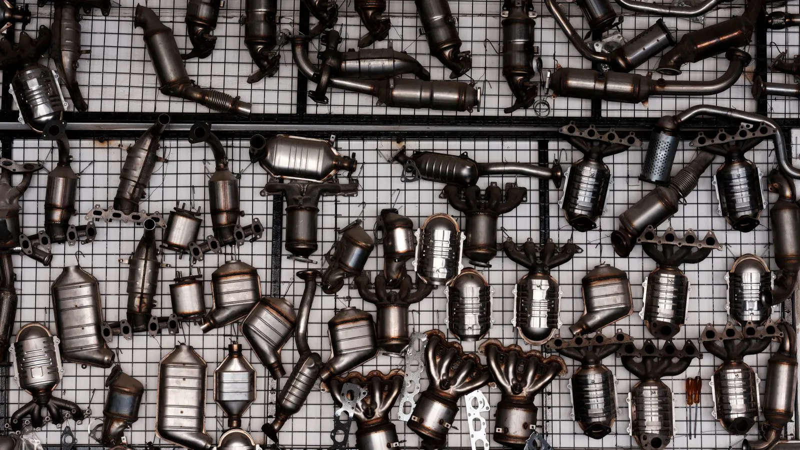
This checklist helps engineers and importers verify automotive cnc parts by auditing dimensional accuracy, material traceability, surface finish, and compliance documentation. It identifies specific red flags and inspection points to prevent defective parts from entering production lines.
- Verify material traceability through heat numbers and mill certificates before accepting parts.
- Check dimensional tolerance against the drawing, not just the general tolerance class.
- Inspect surface finish and tooling marks that can affect corrosion resistance or seal seating.
- Request first-article inspection reports and process capability studies for critical features.
- Confirm compliance with specific automotive standards like IATF 16949 and material specifications.
Why Automotive CNC Parts Require Different Verification
Automotive CNC parts face stricter quality demands than consumer or industrial components. A single bad bracket can crack a control arm. A warped housing can leak coolant. Buyers and engineers need a structured audit method before releasing parts to production.
This checklist targets the failure points that cause recall risk, warranty claims, and line stoppages. It assumes you have the drawing, the part, and access to the supplier’s documentation. Use it as a gate between sample approval and bulk production. The stakes differ significantly from a consumer product. An automotive part often operates under constant vibration, thermal cycling, and high stress. It must last for the lifetime of the vehicle, not just a few months. A failure at the road test stage is expensive. A failure in the field is a legal and reputational disaster.
The audit must be rigorous. It requires more than visual inspection. You need hard data, traceable records, and physical verification. The goal is to confirm that the part is not just “close enough” but exactly what the engineering team designed. This document provides a step-by-step method to execute that verification.
Section 1: Documentation and Traceability Audit
Before touching the part, pull the paperwork. Automotive suppliers must prove where the material came from. Without this, you cannot trace a defect back to a specific heat or batch. Traceability is the backbone of automotive quality. If a failure occurs, regulators and customers demand to know the exact source of the material.
- Request the material mill certificate. It must match the part’s heat number. If the certificate shows a different material grade than the drawing, reject the lot. For example, if the drawing calls for 4140 steel and the certificate lists 1045, the mechanical properties will be wrong. The part may not hold up under load.
- Verify the supplier’s quality certification. Look for evidence of IATF 16949 or equivalent automotive quality management system. This is not optional for OEM parts. The certification proves the supplier has a system in place to manage quality, risk, and continuous improvement. It is a baseline requirement for most Tier 1 and Tier 2 suppliers.
- Check the first-article inspection report. This document should list every critical dimension measured on the first piece. It proves the setup was validated before mass production. A missing dimension in the first article is a warning sign. It suggests the operator did not follow the inspection plan.
- Confirm the process capability study. For critical dimensions, ask for the Cpk value. A Cpk below 1.33 suggests the machine cannot hold tolerance consistently. Cpk measures how well the process can produce parts within the specified limits relative to the natural variation of the process. A low Cpk means the part will eventually fail.
- Review the revision history. Ensure the part number and revision match the drawing version you approved. Old revisions cause fit issues. If the drawing was updated to change a hole depth, but the supplier is still machining to the old spec, the part will not fit the mating component.
Red flags: The supplier provides a generic mill certificate without a specific heat number. The first-article report is missing critical dimensions. The process capability study is older than six months.
Section 2: Dimensional Tolerance Verification
Automotive CNC parts must fit mating components with precise clearance or interference. A tolerance of ±0.5 mm is acceptable for a non-critical bracket. It is not acceptable for a piston pin or a camshaft bearing surface. Dimensional accuracy is the primary function of the part. If the dimensions are wrong, the part fails its purpose.
Use a calibrated micrometer, bore gauge, or CMM to verify the following:
| Feature Type | Typical Tolerance Range | Inspection Method | Red Flag |
|---|---|---|---|
| Critical Bolt Holes | ±0.05 mm | Go/No-Go Gauging | Holes are oversized or misaligned |
| Mating Surfaces | ±0.02 mm | CMM or Flatness Gauge | Surface is wavy or out of plane |
| General Dimensions | ±0.1 mm | Calipers or Micrometer | Dimension is outside drawing limit |
| Threaded Features | Per drawing spec | Thread Ring Gauge | Threads do not engage smoothly |
| Chamfer/Radius | ±0.05 mm | Visual and Caliper | Sharp corners remain unbroken |
Red flags: The supplier measures with a single-point gauge instead of a full CMM scan. Critical features are not measured. The supplier uses a tolerance class that does not match the drawing.
Section 3: Surface Finish and Tooling Marks
Surface finish affects corrosion resistance, seal seating, and aesthetic quality. A rough finish traps dirt and moisture. It also wears mating parts faster. Surface quality is often overlooked in initial checks, but it has long-term consequences. A rough surface creates friction. Friction generates heat. Heat degrades seals and lubricants.
Inspect the following:
- Check for chatter marks. These are wavy lines caused by vibration during machining. They weaken the part and increase friction. Chatter is often caused by an unstable workpiece or a dull tool. It is a sign of poor process control.
- Look for tool marks. Deep grooves from the cutter can score the surface. They create stress concentration points. These points are where cracks start to form. In a high-stress environment, a scored surface can lead to fatigue failure.
- Verify the Ra value. The drawing should specify a roughness average. If it is not specified, use the drawing’s general tolerance or industry standard. Ra is a measure of the average height of surface irregularities. A lower Ra value indicates a smoother surface.
- Check for heat discoloration. Darkening on a machined surface indicates excessive heat. This can alter the material’s hardness. Heat discoloration is a sign that the cutting tool is generating too much friction. It can lead to a hardened surface that is brittle and prone to cracking.
- Inspect for burrs. Sharp edges on holes and slots can cut operators and damage mating parts. Burrs are also a safety hazard. They can snag clothing or hair. They can also catch in assembly mechanisms and cause jams.
Red flags: Visible chatter marks on a flat face. Deep tool marks on a sealing surface. Heat discoloration near a threaded feature.
Section 4: Material Hardness and Heat Treatment
Some automotive CNC parts require heat treatment to achieve specific hardness. A soft gear will wear down. A hard bearing race will crack if over-hardened. Hardness is a critical mechanical property. It determines how well the part resists wear and deformation.
- Request the hardness test report. It must show the value in HRC or HV. The test must be performed on the specific part, not just a sample from the same batch.
- Verify the test location. The hardness test must be performed on the specific area that will experience load. Testing a non-critical area is useless. The hardness can vary across the part due to the heat treatment process.
- Check for distortion. Heat treatment can warp a part. Measure the part again after heat treatment to ensure it still fits. Distortion is a common problem with heat treatment. If the part warps, it may not fit the mating component.
- Confirm the quenching medium. Some materials require oil quenching. Water quenching can cause cracking. The quenching medium is a critical variable. Using the wrong medium can ruin the part.
Red flags: The hardness value is outside the drawing specification. The part is warped after heat treatment. The supplier cannot identify the heat treatment process.
Section 5: Corrosion Resistance and Coating
Automotive parts operate in salt, water, and chemical environments. Coatings protect the metal. But a bad coating can fail early. Corrosion is a major cause of part failure. It weakens the metal and can lead to structural failure.
- Check the coating type. The drawing should specify the finish, such as zinc plating, black oxide, or anodizing. The coating must match the specification. A different coating may have different corrosion resistance properties.
- Perform a salt spray test. This simulates years of road salt exposure. If the coating fails in 48 hours, it is not suitable for exterior parts. The salt spray test is a standard method for measuring corrosion resistance.
- Inspect for coating porosity. Pinholes in the coating allow corrosion to start. Porosity is a defect in the coating process. It can be caused by poor surface preparation or an improper coating thickness.
- Check adhesion. A coating that flakes off is useless. A simple scratch test can reveal weak adhesion. Adhesion is critical. If the coating does not bond well to the base metal, it will fail.
- Verify the coating thickness. Too thin a layer fails. Too thick a layer can interfere with tight fits. Coating thickness is a critical dimension. It must be within the specified range.
Red flags: The coating is peeling at the edges. The salt spray test shows rust within the specified hours. The coating thickness is below the drawing specification.
Section 6: Final Assembly and Fit Check
The part must function in the assembly. A part that meets every dimension on paper can still fail if it does not fit the mating component. Fit is the ultimate test. It confirms that the part works in the real world.
- Perform a fit check. Assemble the part with its mating component. Check for gaps, interference, and movement. The part should assemble easily. It should not require force.
- Check for binding. If a shaft or pin does not move freely, the tolerance is too tight. Binding is a sign of a dimensional issue. It can cause wear and failure.
- Verify fastener access. Ensure bolts and nuts can reach their locations. Fastener access is a common issue. If a bolt cannot reach its hole, the part is defective.
- Check for interference with wiring. The part must not pinch or damage nearby cables. Wiring is sensitive. A sharp edge or a protruding feature can damage it.
- Inspect for debris. Machining chips and coolant residue must be removed. They can damage other components. Debris is a common issue in assembly. It can cause jams and failures.
Red flags: The part requires force to assemble. The part blocks access to a bolt hole. The part vibrates during simulation.
Section 7: Supplier Responsiveness and Corrective Action
A good supplier reacts to defects. A bad supplier blames the drawing. Your audit includes how the supplier handles issues. Supplier responsiveness is a key indicator of quality. A good supplier will work with you to solve problems. A bad supplier will make excuses.
- Ask about their corrective action process. They should have a defined method for fixing non-conforming parts. Corrective action is a standard practice. It ensures that defects are identified and fixed.
- Review their change control. If they change the tool, the machine, or the material, they must notify you. Change control is critical. Any change can affect the part’s quality.
- Check their warranty terms. A short warranty indicates low confidence in the part. Warranty is a sign of confidence. A good supplier will stand behind its parts.
- Verify their capacity. If they are at full capacity, quality control may be rushed. Capacity is a risk factor. A supplier that is overworked may make mistakes.
- Ask about their inspection equipment. They should have calibrated tools that are maintained regularly. Inspection equipment must be accurate. If the tools are not calibrated, the measurements are wrong.
Red flags: The supplier cannot explain their corrective action process. They make changes without notification. The warranty is less than 90 days.
Final Inspection Gate
Before releasing the lot, complete this final gate:
- All documentation is present and matches the drawing.
- All critical dimensions are within tolerance.
- Surface finish meets the drawing specification.
- Hardness and heat treatment are verified.
- Coating is intact and passes the salt spray test.
- The part fits the mating component without force.
- The supplier has agreed to their corrective action process.
If any item fails, hold the lot. Do not release parts to production. A small defect now costs more than a delay now.
Frequently asked questions
What is the most common reason automotive cnc parts fail?
Dimensional drift due to uncontrolled tool wear. The tool expands or contracts during the run, causing the part to drift outside tolerance.
How often should I request a first-article inspection report?
Request it for every new part number and every major revision. Do not rely on the previous lot's report if the setup changes.
Is a CMM always required for inspection?
No. Simple parts can be checked with calipers and gauges. But for complex parts with multiple critical features, a CMM scan is the standard.
What if the supplier does not have a mill certificate?
Reject the lot. You cannot verify the material composition. This is a non-negotiable failure for automotive parts.
How long should a first-article report remain valid?
Until the setup changes. If you change the tool, the machine, or the operator, the first-article report is invalid and must be redone.