CNC Milling vs Turning: Which Fits Your Part
Choose between cnc milling vs turning based on part geometry. Turning suits rotational parts, while milling handles complex shapes. This guide outlines the key differences to help engineers select the right cnc machining method for their specific requirements.
- Select turning for parts with rotational symmetry and cylindrical features.
- Choose milling for complex geometries, pockets, and non-circular shapes.
- Consider material thickness and tolerance requirements when comparing cnc milling vs turning.
- Evaluate tool access and fixturing constraints before finalizing the process.
- Review the part drawing for features that favor one process over the other.
Start with the part shape, not the tool
The first step in CNC process selection is looking at the raw geometry. If the part revolves around a central axis, turning is usually the starting point. If the part has flat surfaces, pockets, or irregular contours, milling takes over. Many engineers assume the process choice is a simple matter of cost. In practice, the shape of the part drives the decision more than the budget. A cylinder with a chamfer is easy to turn. A block with a complex internal thread is not.
When reviewing a drawing, check the axis of symmetry. Does the part look like it could be mounted on a chuck? If yes, turning becomes the primary option. If the part has multiple flat faces, bosses, or through-holes that do not align with a central axis, milling is the better fit. This distinction matters because each process has inherent strengths and weaknesses. Understanding them prevents rework and saves time in the shop. For example, a hydraulic cylinder head might have a circular bore and a central axis, suggesting turning. However, if that same head includes a rectangular mounting bracket on the side, the geometry shifts. The circular bore can be turned, but the bracket requires milling. Ignoring the bracket early in the design phase leads to a second operation that costs time and money.
Turning: strengths and limits for rotational parts
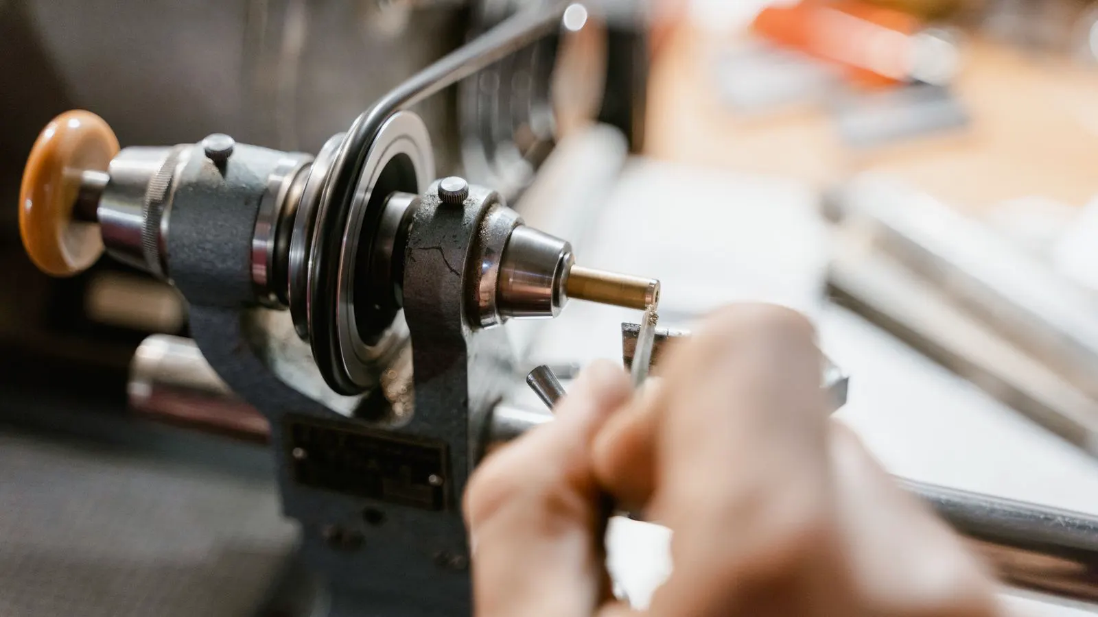
Turning is ideal for parts that share a common axis. Think spacers, bushings, flanges, and shafts. The workpiece rotates while the tool stays fixed. This setup provides excellent surface finish on cylindrical surfaces. Tolerances on diameters are usually tight. The process is fast for simple profiles.
The main limitation is geometry. Turning cannot create flat faces, slots, or pockets easily. If the design includes a rectangular cutout or a non-circular profile, you are moving outside the core capability of a standard lathe. Some centers can perform milling operations, but the setup and tooling change. For a pure turning job, the part should be round. If the drawing shows a square or hexagonal profile, that is a strong signal to look at milling instead. Consider a drive shaft for an automotive application. It typically has a round body, a tapered end, and a splined section. These features are concentric and perfectly suited for a lathe. The tool can cut the taper and the splines while the shaft spins. Adding a flat keyway to the side would break the rotational symmetry. The lathe cannot cut a flat line across the rotating part without complex indexing or secondary tooling. That complexity often makes the process less efficient than simply moving to a mill.
Milling: the flexible workhorse
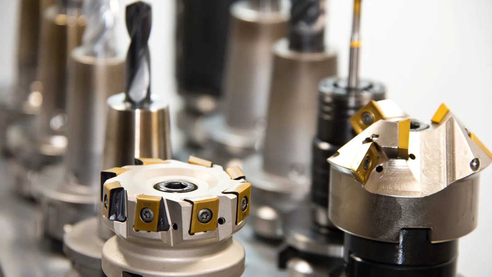
Milling works by rotating the tool and moving it across a stationary workpiece. This gives the operator access to almost any contour. Pockets, slots, contoured faces, and complex 3D shapes are all within reach. A single 3-axis or 5-axis mill can produce features that would require multiple setups on a lathe.
The trade-off is speed and simplicity. A flat surface on a mill may take longer to rough out than a turned cylinder. Tool access is a constant consideration. Deep pockets require long tools that are prone to deflection. The workpiece must be held firmly, often with clamps or a vise. This can limit the size of the part or the direction of the cut. Engineers must design with these constraints in mind. Take a complex bracket for a machine tool. It might have a deep central pocket for a motor mount, flanges on three sides, and a series of small holes for fasteners. A lathe would struggle with the flanges and the pockets. A 3-axis mill can handle the flanges and the shallow holes. If the pocket is deep and narrow, the tool length becomes a critical factor. The operator must choose a tool short enough to avoid chattering but long enough to reach the bottom. This is a design constraint that must be managed during the CAD phase, not discovered during the first cut.
Compare the options at a glance
The table below summarizes the core differences. It is not a ranking. It is a decision aid.
| Option | Best for | Limitations |
|---|---|---|
| CNC Turning | Rotational parts, shafts, flanges, tight diametric tolerances | Cannot handle flat faces, pockets, or complex non-circular shapes |
| CNC Milling | Complex shapes, pockets, slots, 3D contours, multi-face parts | Slower for simple profiles, requires robust fixturing, tool access limits |
| Combined (Turn/Mill) | Parts with both round and flat features | Higher setup time, more complex programming, potentially higher cost |
| 5-Axis Milling | Complex aerospace or medical parts with multiple angled features | Very high setup cost, specialized tooling, steep learning curve |
| 5-Axis Turning | Complex shafts with angled features and off-axis cuts | Expensive machines, limited availability, specialized programming required |
When to pick turning
Pick turning when the part is primarily cylindrical. If the drawing shows a series of concentric features, turning is the natural choice. The process is efficient because the material removal is consistent. The tool path is simple. The surface finish on the outside diameter is typically superior to what a mill can achieve on a curved surface.
Consider turning for parts with high production volumes. The cycle time is shorter for simple profiles. If you are making ten thousand spacers, turning is almost always the right answer. The setup is quick. The tooling is standard. The process is well understood. The main risk is if the design changes to include a flat face. At that point, the process selection changes. For instance, a simple bushing with a flat spot for a locating pin is a classic turning job. The flat spot is small and can be cut with a parting tool or a special shape tool while the part rotates. However, if the flat spot becomes a large mounting surface with bolt holes, the geometry changes. The turning center would need to index the part multiple times to cut the bolt holes accurately. This indexing introduces error and increases cycle time. In that scenario, moving the operation to a mill or a turn/mill center becomes more efficient. The decision depends on the size of the non-rotational feature relative to the part.
When to pick milling
Pick milling when the part has flat features, pockets, or complex contours. If the drawing shows a plate with multiple holes and slots, milling is the only viable option. The process allows for precise cutting of lines and planes. It is the standard for fixtures, jigs, and structural components.
Milling is also the choice for parts with thin walls. The control over material removal is better. You can cut narrow slots without the vibration issues that can occur on a lathe. The tool path can be optimized to reduce stress on the part. This is critical for thin-walled parts where vibration can ruin the surface finish. A good example is a heat sink fin. The fins are thin, flat, and spaced closely together. A lathe cannot cut a straight line across a rotating part without creating a groove, not a flat face. A mill can cut the fins with a slot cutter or a ball nose end mill. The operator can control the depth of cut and the feed rate to prevent the thin fins from snapping. This control is vital for maintaining the cooling efficiency of the heat sink.
The hybrid approach: turn and mill
Many modern parts are not purely turning or purely milling. They are a mix. A shaft with a flange and a keyway is a classic example. It starts as a turning part. The flange and keyway require milling. Some machines can do both in a single setup. These turn/mill centers are gaining popularity. They reduce the number of setups and handling times. The trade-off is cost. These machines are more expensive to run. They require more complex programming. For low-volume prototypes, the added cost may not be justified. For high-volume production, the reduced cycle time can make it worthwhile.
Consider a valve stem. The stem is cylindrical and requires a tight diameter tolerance. This is a turning operation. The stem also has a flat base for mounting and a small rectangular window for an actuator. These features require milling. A traditional approach would be to turn the stem on a lathe, then move it to a mill to cut the flat and the window. This involves two setups, two tool changes, and potential handling errors. A turn/mill center can do both in one setup. The part is held in a chuck. The lathe cuts the diameter. Then the chuck rotates or the head moves, and the mill cuts the flat and the window. The part never leaves the machine. This reduces cycle time and improves positional accuracy between the turned surface and the milled features. For a production run of thousands of valve stems, this efficiency pays off. For a one-off prototype, the setup time for the complex programming might outweigh the savings.
Material and tolerance checks
The material affects the process choice. Soft materials like aluminum are easy to machine on either process. Hard materials like titanium or Inconel require different tooling. The rigidity of the machine and the workpiece becomes more critical. Turning hard materials can lead to chatter. Milling hard materials requires rigid tooling.
Tolerances also matter. Turning excels at tight diametric tolerances. Milling excels at tight positional tolerances between features. If the drawing calls for a hole location within a few microns, milling is the better choice. If it calls for a diameter within a few microns, turning is the better choice. Reviewing the tolerance stack-up is a key part of the CNC machining methods decision. For example, a hydraulic piston rod in a hard steel alloy requires a tight diameter tolerance to prevent leaks. Turning is the preferred process because the tool is in constant contact with the rotating surface, allowing for precise diameter control. However, if the rod has a shoulder with a flat face that must be positioned accurately relative to the diameter, milling becomes necessary. The material hardness also impacts the process. In titanium, the tool wears quickly and heat builds up rapidly. Turning requires high speeds and low feeds to manage heat. Milling requires rigid fixtures to prevent the part from moving under the cutting forces. The material choice should influence the tooling and the machine selection, not just the basic process type.
Final decision checklist
Before finalizing the process, run through this checklist. First, check the geometry. Is the part rotational or non-rotational? Second, check the features. Are there pockets, slots, or flat faces? Third, check the material. Is it soft or hard? Fourth, check the tolerances. Are they diametric or positional? Fifth, check the quantity. Is it a prototype or a production run?
Each answer points to a process. If the answers are mixed, consider a combined approach. The goal is to select the process that minimizes risk and cost. There is no single right answer. The right answer depends on the specific part. By applying these checks, you can make a confident decision. For a part like a complex aerospace bracket, the geometry is non-rotational, the features include deep pockets and angled holes, the material is titanium, the tolerances are positional, and the quantity is low. The checklist points clearly to 5-axis milling. The part cannot be turned. The pockets require deep tool access. The angled holes require multi-axis capability. The titanium requires a rigid mill. The low quantity means the high setup cost of a 5-axis machine is justified by the single setup requirement. For a part like a steel shaft with a flat keyway, the geometry is rotational, the features are mostly concentric with one flat, the material is steel, the tolerances are diametric, and the quantity is high. The checklist points to turning or turn/mill. The rotational nature favors turning. The single flat feature can be handled by a turn/mill center or a lathe with indexing. The high quantity favors the efficiency of turning. The decision is straightforward when the checklist is applied consistently.
Frequently asked questions
Can a lathe mill a part?
Yes, many modern CNC lathes have milling capabilities. They can perform some milling operations, but they are not a replacement for a dedicated mill for complex shapes.
What is the biggest difference between cnc milling vs turning?
The biggest difference is the axis of rotation. Turning rotates the part, while milling rotates the tool. This fundamental difference dictates the types of geometries each process can handle.
How do I choose the right cnc process for a prototype?
Start with the geometry. If it is round, choose turning. If it is complex, choose milling. For a prototype, prioritize the ability to test the design quickly. Avoid over-engineering the process.
Is turning cheaper than milling?
Turning is often faster for simple rotational parts. Milling is more flexible. The cost depends on the part complexity and quantity. Simple turning parts are usually cheaper. Complex milling parts can be more expensive.
Can I combine both processes in one job?
Yes, turn/mill centers can handle both. This is useful for parts with mixed features. It reduces setup time and handling. It may increase the cost per part.